When a lightning arrester captures lightning, the down conductor immediately rises to a high potential, which can cause side flashovers to conductors around the lightning protection system that are still at ground potential, raising their potential and posing a hazard to personnel and equipment. To reduce this flashover risk, the simplest method is to use equipotential bonding rings to connect conductors at ground potential all the way to the grounding device. Metal facilities, electrical installations, and electronic equipment within the lightning protection station should be equipotentially bonded to the lightning protection system using thicker conductors if their distance from the conductors of the lightning protection system, especially the lightning arrester, does not meet the prescribed safety requirements. This way, when lightning current passes through, all facilities within the station immediately form an "equipotential island," ensuring that no harmful potential difference is generated between conductive components and preventing side flashover discharges. A proper equipotential bond can also prevent backflashovers caused by the rise in ground potential due to lightning current entering the ground.
The purpose of equipotential bonding is to reduce the potential difference between various metal objects and the system within the space requiring lightning protection. When a building houses an information system, in areas where the impact of lightning electromagnetic pulses is to be minimized, the equipotential bonding strip should preferably be made of metal plates and connected at multiple points to reinforcing steel or other shielding components.
The main body for equipotential bonding of all external conductive components entering the building should include the following:
1) The main metal components of the building where the equipment is located and the metal pipes entering the building;
2) Power supply lines, including exposed conductive parts;
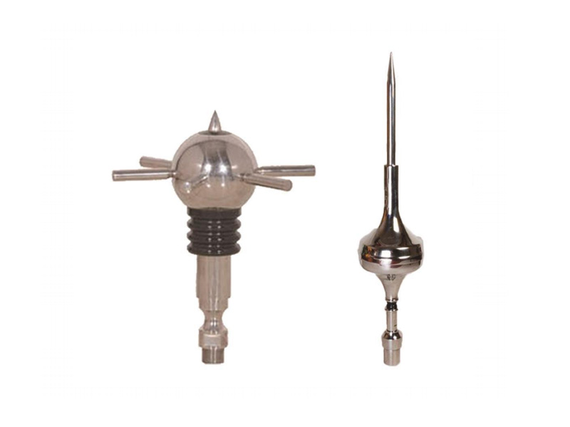
3) Lightning protection devices;
4) Information systems consisting of electronic equipment.
The computer room of the building should be covered with metal shielding mesh on all six sides, and the shielding mesh should be evenly connected to the ring grounding busbar in the computer room at multiple points. The equipment should be directly connected to the nearest equipotential bonding strip with the shortest distance using a star (S-type structure or mesh M-type) structure. S-type structure is selected for small computer rooms, and M-type structure is selected for large computer rooms. Shielded cables should be used as much as possible for power cables and communication cables in the computer room. Overhead power lines should be replaced with shielded cables after being led down from the terminal pole. Before entering the building, they should be horizontally buried for at least 15m, with a burial depth greater than 0.5m. Both ends of the shielding layer should be grounded. Unshielded cables should be run through galvanized iron conduits and horizontally buried for at least 15m, with both ends of the conduit grounded.